I've got a bunch of photos from the work today, mainly dealing with the "T-Nuts" and what they are
(I've been asked privately what a t-nuts is, and how it works). That being said, the pictures mainly focus on those and what's up with them. There's also noticable progress on the project as a whole though....of course.

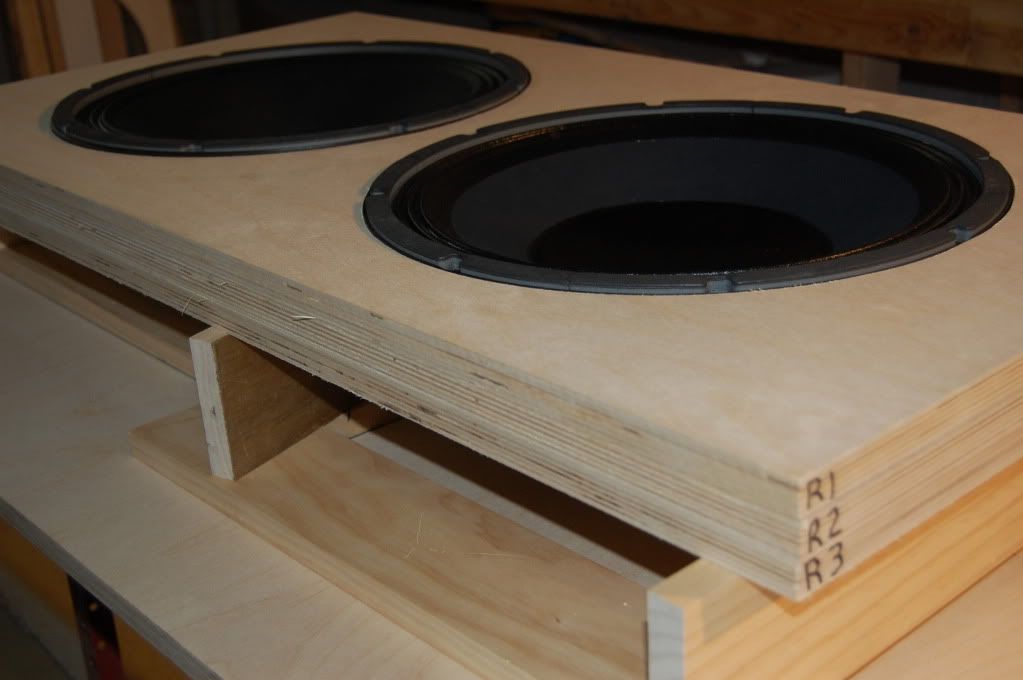
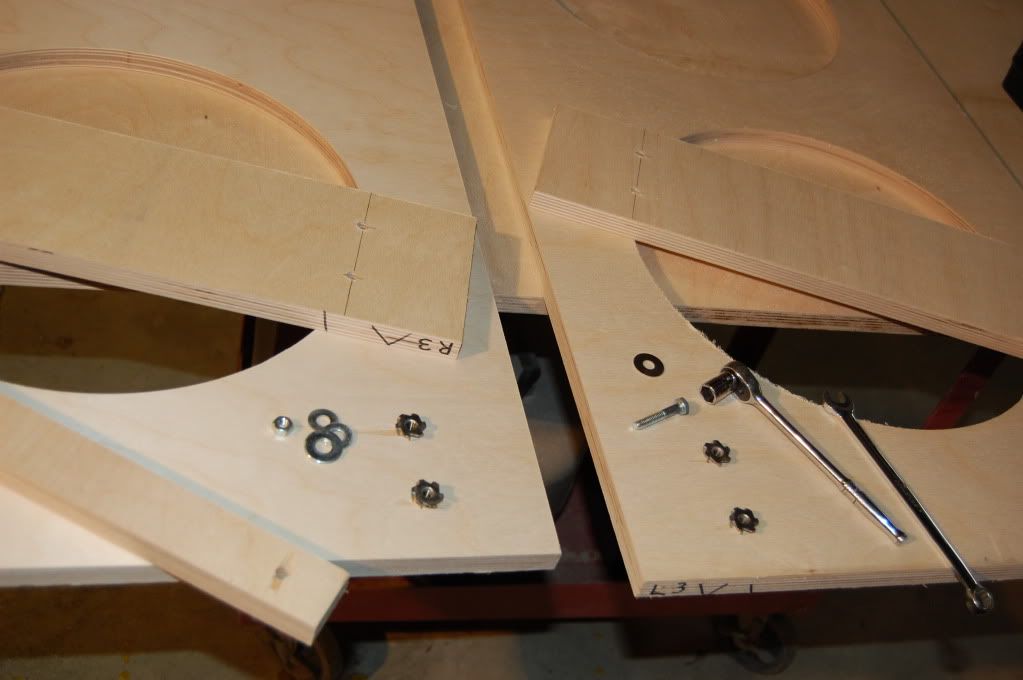
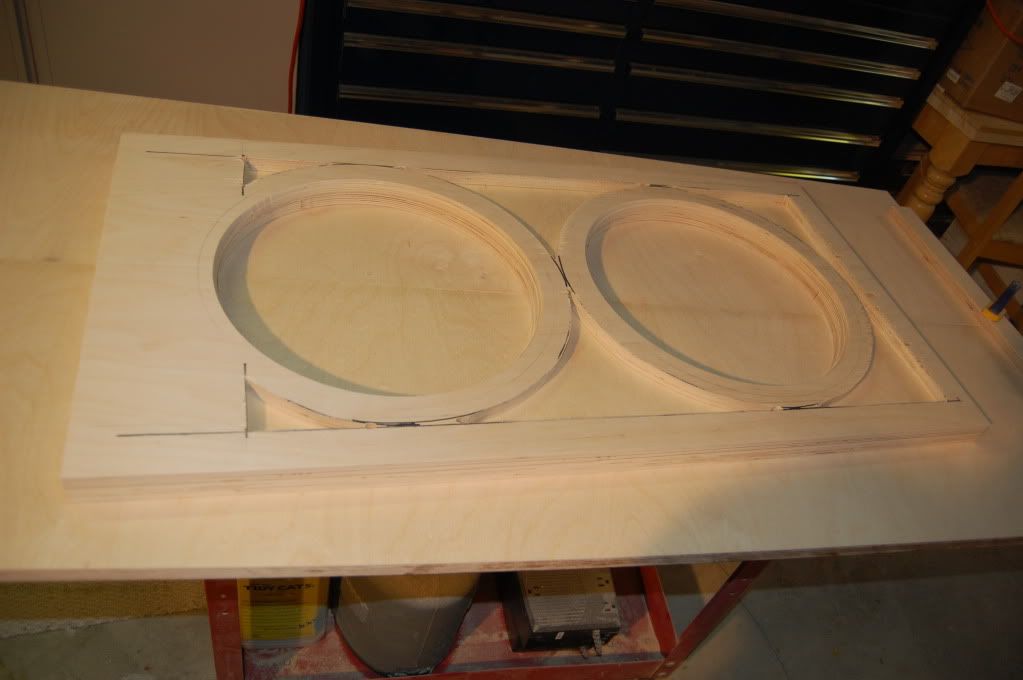
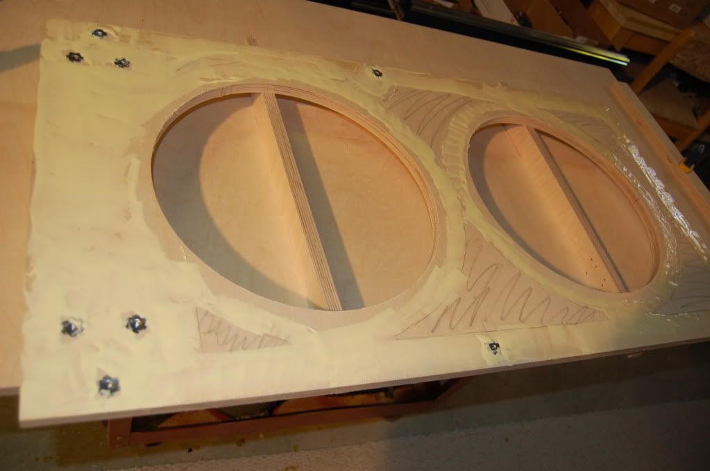
The first pic is a test fit of the two 15" drivers. Of course, now would be a good time to know if they don't fit.
Notice the R1, R2, R3.....The "R" is "Right speaker" and the number is it's position in the layers.
- Number 1 is the face (front) of the speaker.
- Number 2 will be the one that is hollowed out for the sand. Middle.
- Number 3 is the back.
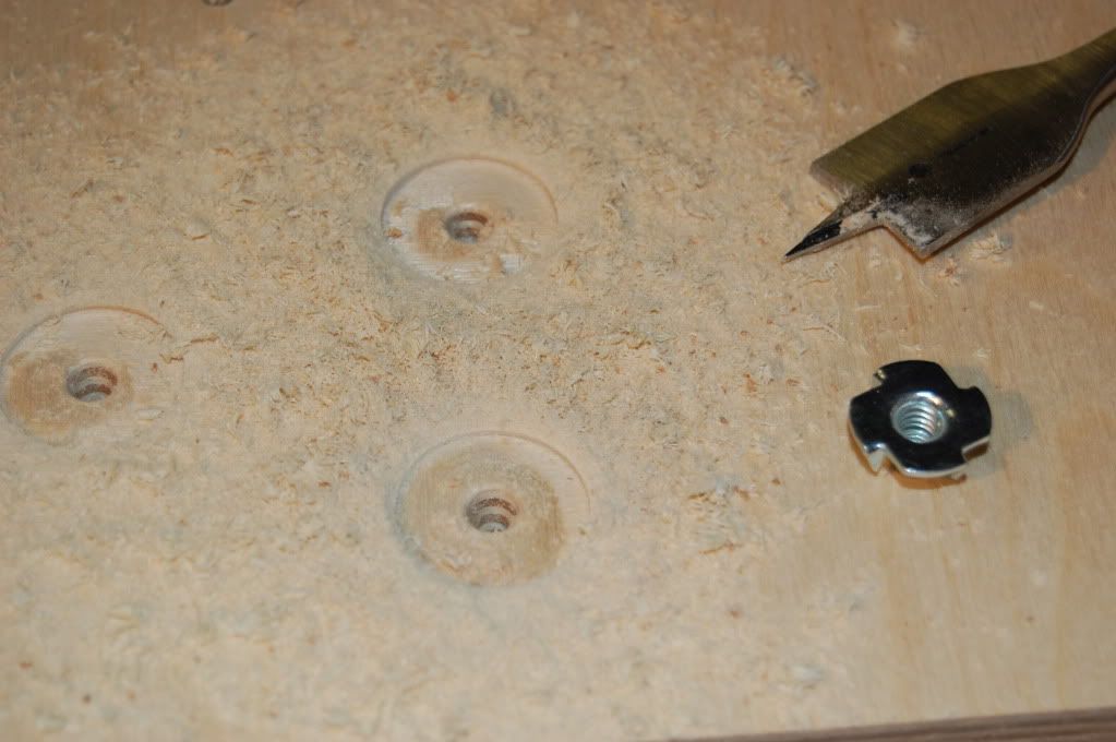
Next up, the t-nuts, their location, how they're pre-drilled and what a t-nut looks like in general.
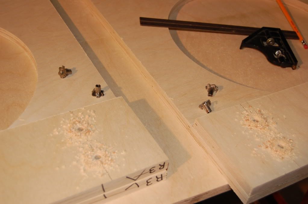
Here's the t-nut in place, before it's been drawn down into the wood.
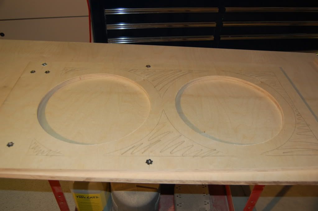
In the background are the pieces of wood that will be the front plates that will house the amps and crossovers. This is the piece of wood that will attach to the speaker baffle directly, and hold the two together.
After that, I'll just shut up, stop talking and show a few pictures. They should speak for themselves.
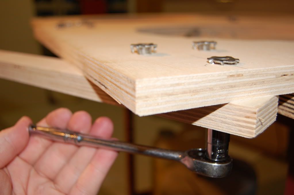
This one needs a few words.....
The heads of the t-nuts are not flush, and in a situation where the t-nut must "disappear" totally, 100% on both sides, you have to give the layer behind it some room.
The easiest way to do that would be to use a paddle bit so the head of the t-nut has a "void" to go into.
That can be done on the piece of wood the t-nut goes into, or the piece of wood that will be meshing with the t-nut, whichever you prefer.
Personally, I like to leave as much material as possible for the t-nut to attach to. If you cut a bunch of wood out to accomidate the t-nut, you've weakend the material. And if you're using expensive material like this, that would be a shame.
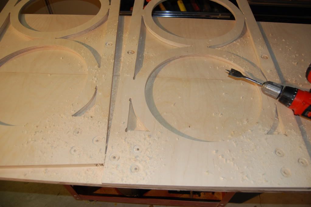
Time to blow the saw dust away, get things cleaned up (yes, I actually do vacuum the floor of the workshop before I do this)
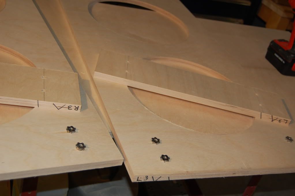
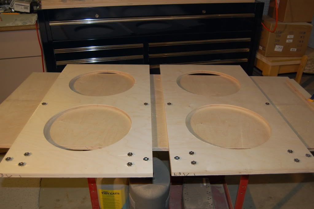
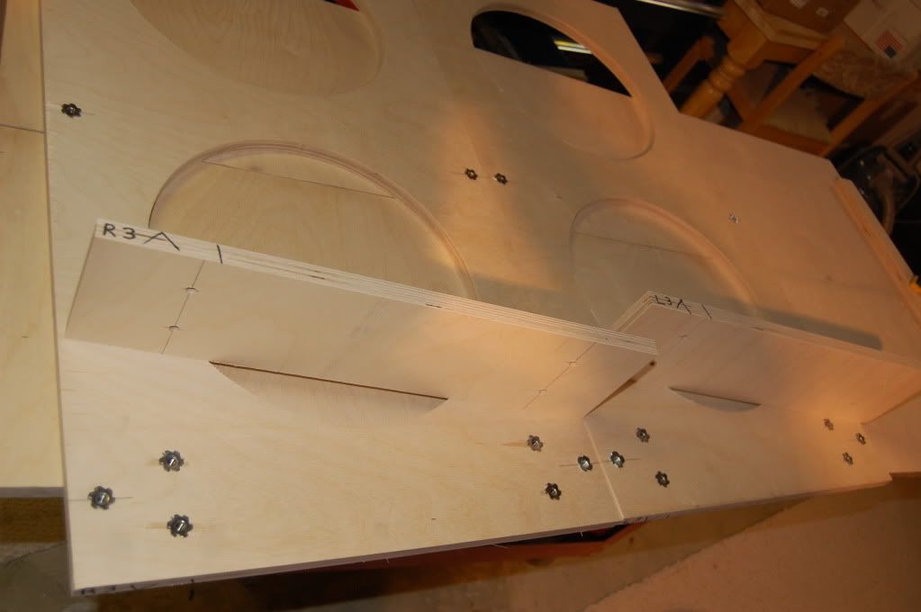
In the previous picture, I put layer #2 on top of layer #3, and traced around the openings.......(scroll back up a bit)
These open areas will NOT receive glue during the next step.......(now scroll down)
The zig-zag pencil marks will not get glue.
Also note, that I didn't get too close to the opening of the where the driver will mount to. No glue will (ever) be needed there.
Alright, now we're getting somewhere.
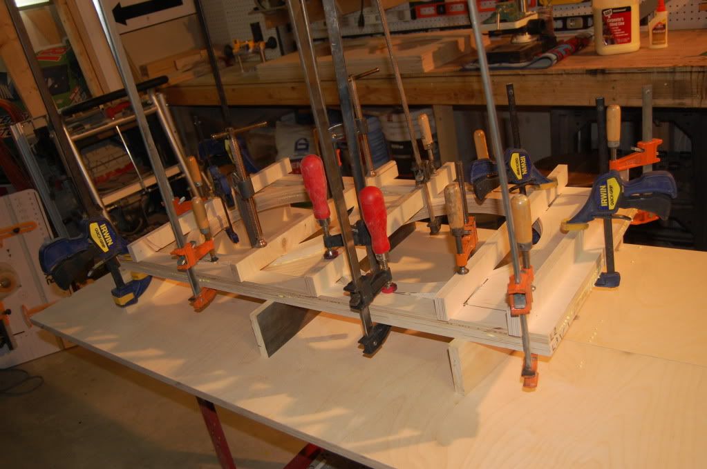
It's glue time, so my priority here was just that, not taking pictures.
Bam
No man has ever died with too many clamps.
Done for the weekend. See you next Saturday. Buh Bye......